

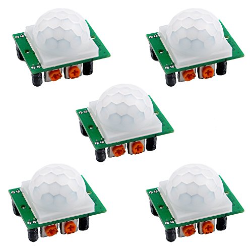


DIYmall 5 Pack HC-SR501 Pir Motion IR Sensor Body Module Infrared for Arduino
$9.49
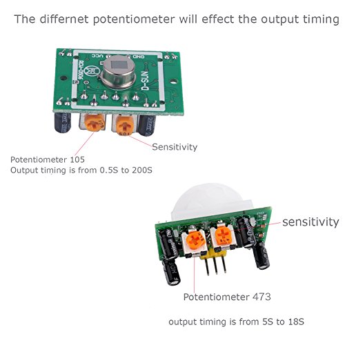
- Use Potentiometer 105, output timing is from 0.5S to 200S. Same product link https://www.amazon.com/dp/B07CSM3K63
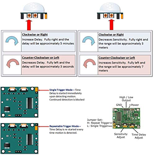
- NOTE: On this retrigger jumper is a solder jumper, and you need solder it by yourself
- Pls note that there is no IR emitter in this module, the principle of PIR sensor is to detect the infrared radiation emitted by the human body, it only have a IR sensor (cell)
- Package Included: 5 X HC-SR501 PIR Infared Sensor. If any question, pls contact us by email. You can find ” Sold by DIYmall” under Buy Now button, click “DIYmall” and you will get to a new page, click “Ask a question”.
Specification: DIYmall 5 Pack HC-SR501 Pir Motion IR Sensor Body Module Infrared for Arduino
| Product Dimensions | 1.18 x 0.98 x 0.79 inches |
|---|---|
| Item Weight | 1.58 ounces |
| Item model number | 4331029690 |
| Is Discontinued By Manufacturer | No |
| Date First Available | September 23, 2013 |
| Manufacturer | DIYmall |
8 reviews for DIYmall 5 Pack HC-SR501 Pir Motion IR Sensor Body Module Infrared for Arduino
Add a review
Related Products
Added to wishlistRemoved from wishlist 0

Added to wishlistRemoved from wishlist 0

Added to wishlistRemoved from wishlist 0
Handy Forms –
This is probably the most common PIR sensor available. It’s easy to use, and quite sensitive. But before you build your project around one, I suggest you set up a test to see whether they are reliably reporting detection or perhaps over-reporting. Of the 5 purchased, 2 of them consistently reported people that just weren’t there (or perhaps reported ghosts?). Setting all 5 to maximum sensitivity, first I tested to be sure that all 5 detected motion – they did. Then I aimed them at a wall and let them report hourly detections all night with no one around. One reported an average of 45 detections per hour, another saw about 15, and the other 3 reported zero. Apparently 2 have a more vivid imagination than the others. So, 2 went in the trash and 3 are usable. I guess at about 2 bucks apiece, 3 out of 5 shouldn’t be a surprise. I would give 5 stars to the 3 good ones, and 1 star to the other 2, for an average of 3.4 — but feeling generous and considering the low cost, I rounded up to 4.
Xwin –
Tried 3 sensors out of 5 and none of them worked with Arduino Uno WiFi Rev2. I thought that Arduino could not supply enough voltage but measuring with a multi-meter I registered 5.01V. Two of the units brought output pin high couple of times but then no motion was detected. Remaining unit had output pin high at all times. I took one unit to work and hooked it up to a bench power supply and a scope and it behaved the same from 5V to 8V. Scope registered high at all times on the output. I did not even open the remaining units and just sent them all back. It could have been a bad luck but what are the chances that all 3 randomly picked units out of 5 would not work.
Linda –
Hooked the VCC and ground to a 12v A/C adapter and it worked perfect. The 3.3v “trigger” pin (the “OUT”) even had enough juice to directly power a red LED (tho a little dimmer than normal). Very wide sensitivity pattern. Tho description says “< 100 degrees" I thought it was greater than 120.
At default sensitivity it would trigger easily from 8-10′ away. I never adjusted it as that was the perfect distance for my needs.
Holding it with the sensor “dome” facing down and the adjusting (orange) “screws” facing you, the left one is the sensitivity, the right is the duration that the OUT pin will stay “on” (i.e. hold at 3.3v). Minimum seems to be around 4 seconds.
Peter R. –
Works as it should. NOTE: if you solder the jumper pad for the re-trigger then you need to cut the trace on the other pad or it won’t work at all. The instructions don’t mention this, and aren’t really clear about what “re-trigger” means.
Paul C. Allsopp –
These modules are perfectly good for most applications they are intended for. If you want very close movement (2 meters to 2 millimeters) you need to sonic ones.
I tested these with an ESP-12 and have great results. For those complaining about false positives, and unreliable readings…
When you switch a GPIO pin to an input and hang a long wire off it, that wire can pick up stray signals and cause the voltage on the GPIO pin to vary. This can cause the system to think the switch has changed.
To fix this, there are several things you can do.
1. add a pull-up resistor
2. add a bypass capacitor
3. shielding on the wire
4. use twisted pair wiring
A pull-up resistor is a resistor connected between the GPIO pin and 3.3v. The exact value of this is not critical, 4.7k is a common value to use, as is 10k. This ensures that when the switch it open, the GPIO pin will go high.
A bypass capacitor is a small (pF range) capacitor that is connected between the GPIO and ground. This provides a path for any radio signals that are picked up by the wire to go to ground and not confuse the system.
Shielding or using twisted pair wiring are other ways to reduce the effect of radio signals on the system.
A. Marks –
I pulled the protective plastic bubble to see which pin is GND, 5V, and OUTPUT. Wired them to my Arduino. Set the pin as INPUT, and again as INPUT_PULLUP, and it never budges from HIGH. Checked around online for clues, tried those I found, but these things seem useless. First Arduino sensor / component / anything in 5 years that was JUNK out of the foil pouch. Say hello to my little dumpster…
AB –
Nice PIR sensor and good price for 5. Well packaged, all 5 work. Jumpers on the High/Low setting and more doc links here would have helped earn the fifth star.
Best docs I’ve found can be found by googling “henrysbench HC-SR501 Arduino Tutorial and Manual” (Amazon won’t let me post a direct link)
Two things worth noting:
– Without any changes to jumper settings these are set in High (repeat) mode
– Running them even SLIGHTLY under 5v may cause repeat false triggers (i.e. “flashing” on/off on the output signal)
Tim Heisler –
Timeout delay only goes from 5s to 9s. Far from the advertised 0.3 to 200s.
Revised review: I still think the description is misleading, but I was able to achieve my desired results by de-soldering the Tx potentiometer and soldering in my own resistor of the necessary size.